- FORWARD AND REVERSE MOTOR STARTER HOW TO
- FORWARD AND REVERSE MOTOR STARTER PDF
- FORWARD AND REVERSE MOTOR STARTER FULL
- FORWARD AND REVERSE MOTOR STARTER SOFTWARE
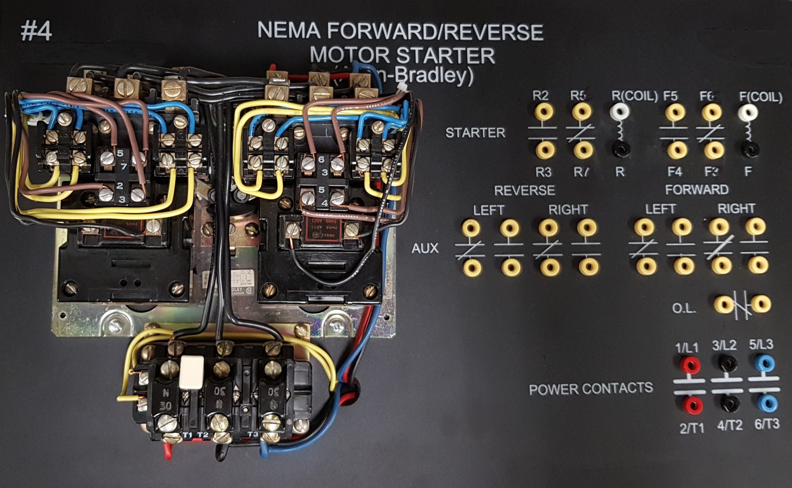
Oa 1208 forward reverse motor starter wiring diagram on ot 0476 control circuit together with and latch in one of two states either energized or dv 6417 dc timer ic re verse developing a 3 phase using plc ladder logic tutorials point electric giant 6balmoond ge 8479 power Oa 1208 Forward Reverse Motor Starter Wiring Diagram On Ot… Read More » Notes: Your question is about the control circuit which is the wiring to the push buttons and/or switches and other devices that turn on a motor and choose which direction it will run. The motor runs to the right with the relay de-energized as shown. This PWM motor control circuit provides many controls for DC motor. This is the PWM Speed DC motor Rotation circuit. DISCLAIMER: All wallpapers and backgrounds found here are believed to be in the "public domain". Isn’t it very simple? Some boards to consider are: 12Vdc 1-Channel Isolated IO DPDT Relay Board Module (CT024) We use 2 'magnetic contactors' as forward reverse switch. A wiring diagram is a simplified conventional pictorial representation of an electrical circuit.
FORWARD AND REVERSE MOTOR STARTER SOFTWARE
A platform to learn electrical wiring, single phase, 3 phase wiring, controlling, HVAC, electrical installation, electrical diagrams, kindly share which software have you used for it. The circuit can drive brushed DC Motor with up to 12 A peak current. It reveals the components of the circuit as simplified forms, as well as the power as well as signal links in between the tools.
FORWARD AND REVERSE MOTOR STARTER HOW TO
Learn How to Design schematics adn diagram, Toyota Camry 2018 Electrical Wiring Diagram, 2007 Toyota Camry Electrical Wiring Diagram, Vt Commodore Headlight Switch Wiring Diagram, 3 Phase Electric Duct Heater Wiring Diagram. The motor is DC 20v and as mentioned above is run through a speed control which i'm presuming is working as a variable resister rather than pulsing, the forward and reverse feature is part of the trigger assembly but seems to be a simple switch that reverses the polarity to the motor. Forward and backward motor and battery wiring diagram. In short this the complete guide of forward reverse starter wiring and installation.
FORWARD AND REVERSE MOTOR STARTER PDF
Relays control forward, stop and reverse action, and the motor cannot be switched from forward to reverse unless the stop switch is pressed first: DC motor speed control DC motor speed controller, pdf file A DC motor. Notice that the control section is … You can control the DC motor to rotate forward, reverse, or break until it stops. Most of the images displayed are of unknown origin.
FORWARD AND REVERSE MOTOR STARTER FULL
How to teach Automatic reverse forward motor control with full practical In this video we can see you that how the electrical circuit of "3 phase motor" is controlled and we can see you full practical video of this circuit and we are explain this circuit with diagram The DC motor speed varies as applied input voltage varies.

A Power supply that suits the specs of the motor (has the voltage and amperage as the manufacturer of the motor recommends).

The interlock contacts installed in the previous sections motor control circuit work fine, but the motor will run only as long as each push button switch is held down. Figure 1 – Hardwired forward/reverse motor circuit. In … So in this circuit if Q1 and Q4 are turned ON simultaneously the motor will rotate forward and if Q2 and Q3 are turned ON then motor will rotate reverse. Low-voltage protection can be implemented using the overload contact input so that, if an overload occurs, the motor circuit will turn off. Control Signal DC Voltage / Motor Reversing Switch. The circuit requires 3 input signals: Enable for PWM input for speed control, IN1 and IN2 to change the motor direction and to apply the brake while the motor is in running condition. A very cool and easy DC motor speed controller circuit … It consists of a DPDT relay, two SPDT limit switches, and 5 diodes. This wiring diagram shows how to configure a DPDT switch as an H Bridge configuration for reversible blind and shade tubular DC motors. If you are the rightful owner of any of the pictures/wallpapers posted here, and you do not want it to be displayed or if you require a suitable credit, then please contact us and we will immediately do whatever is needed either for the image to be removed or provide credit where it is due.

How do you wire a 12V dc motor for forward and reverse using 2 micro switches.? It can Forward-Reverse and Regenerative Braking function.


 0 kommentar(er)
